
flexible circuits assemblies
A flex circuit is more delicate than a rigid PCB, making it susceptible to damage during manufacturing and assembly. Whether due to manufacturing processes or handling in the field, this damage can result in poor performance and reliability for end-users. To avoid this, manufacturers should follow these steps to ensure a quality flex PCB assembly.
Work with a CM to optimize the design for manufacturing process (DFM). This step is essential in ensuring your final product is reliable. The best way to do this is to utilize a DFM software tool, which provides real-time data from the manufacturing equipment and allows you to see how changes affect the product in real-time. This tool can also be used to identify potential issues and mitigate them before the start of production.
Minimize component size and weight to reduce the impact on mechanical reliability. Large or heavy components can increase the stress on the flexible material over time, which can lead to material fatigue and reduce longevity and reliability of the flexible circuits. To minimize this risk, you can design your product with a large number of smaller, lightweight components and consider the use of low-profile connectors.
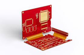
How do you ensure reliability in flexible circuits assemblies?
Incorporate stiffeners strategically to protect the flex region from mechanical stress and ensure proper function and long-term durability of the circuit. Stiffeners can be integrated in a variety of ways, including as part of the mounting holes, or attached with adhesives to the edge of the board. This can help minimize strain and mechanical stress, which is especially important for regions with large components or mezzanine connectors that are prone to mechanical stress from vibration or impact.
Ensure the flex area is shielded to prevent stray capacitance between the same traces. This is a common problem with high-speed flex circuits, which can result in a loss of signal power. To solve this, a flex circuit can be shielded by placing copper in the flex layer or using a conductive epoxy. To reduce cost, you can even use a bare copper surface to achieve the same results.
Understand that flex materials experience more movement and contraction during manufacturing than a traditional rigid PCB, so it’s crucial to keep the drill-to-copper distance as high as possible to ensure maximum reliability. You can also opt for pad-only plating (button plating) instead of panel plating to reduce copper consumption, improve etch yields and control, and maintain consistent conductor thickness and etch patterns for high-speed applications.
Lastly, make sure to run ESD and EMP testing, moisture resistance tests, and a flex bend test on every PCB before sending it out for assembly. This will allow you to identify any areas that may need additional reinforcement or protection from mechanical stress, and ensure your flex PCB is ready for its intended application. If you’re concerned about the reliability of your flex PCB, contact us to learn more about how we can provide you with a turnkey solution. Our experienced CMs have the expertise to ensure a high-quality, reliable flex circuit assembly.